RG-03H Gateway and Ai-LoRaWS-1001 Temperature and Humidity Sensor User Manual
1. Software Function Overview and Usage Instructions
1.1 Function Overview
- Protocol and Network Join Method
Both the RG-03H gateway and Ai-LoRaWS-1001 temperature and humidity sensor support the standard LoRaWAN protocol with only OTAA activation and default support for the TTN server.
- Channel Characteristics
All devices operate on a single channel.
- Frequency Band Configuration*
RG-03H Non-PA Version Gateway
Default frequency band: EU868, and default channel frequency: 868.1 MHz
Supported frequency bands: EU868, AS923, RU864, KR920
RG-03H PA Version Gateway
Default frequency band: US915, and default channel frequency: 902.3 MHz
Supported frequency bands: IN865, AU915, US915
Ai-LoRaWS-1001 Temperature and Humidity Sensor
Firmware-selectable bands: EU868, US915
Supported frequency bands: AS923, RU864, KR920, IN865, AU915
Operating channel must be fully aligned with the gateway
- Customization Requirements
For other frequency band requirements, please contact Ai-Thinker technical support.
1.2 Supported Device Usage Instructions
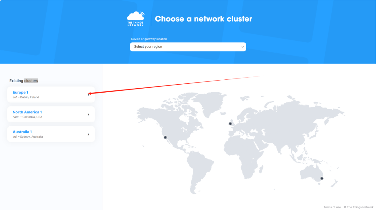
Step 1: TTN Platform Account Registration and Region Selection
Register a personal/enterprise account on TTN Platform.
After logging in, click to enter the console. Since the gateway is configured for the Europe region by default, select the Europe region in the console.

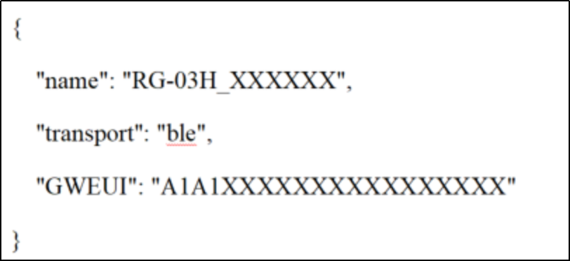
Step 2: Obtain Gateway EUI
Scan the QR code on the RG-03H enclosure to obtain the Gateway EUI (refer to QR code data format description).
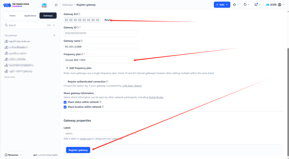
Step 3: Register Gateway on TTN Platform
- Complete the gateway registration on the TTN platform.

- Select the gateway operating frequency band: Europe 868.1 MHz.
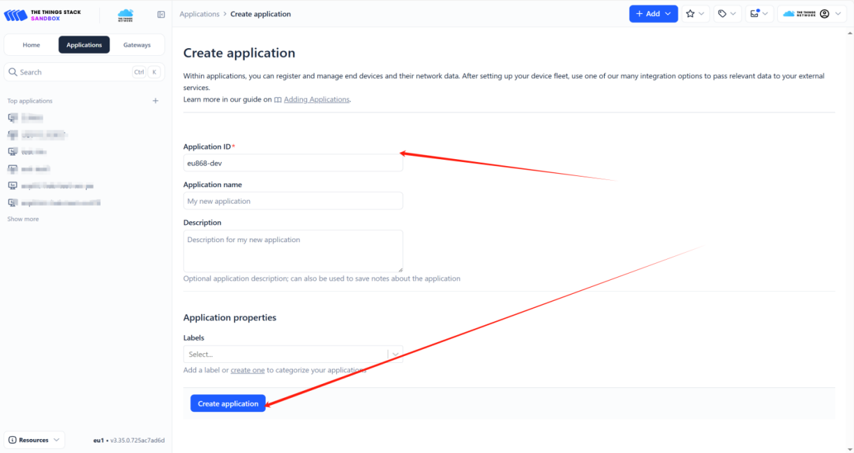
Step 4: Create TTN Application
Create an application in the TTN console and configure basic information such as application ID and name.

Step 5: Obtain Node Network Join Parameters
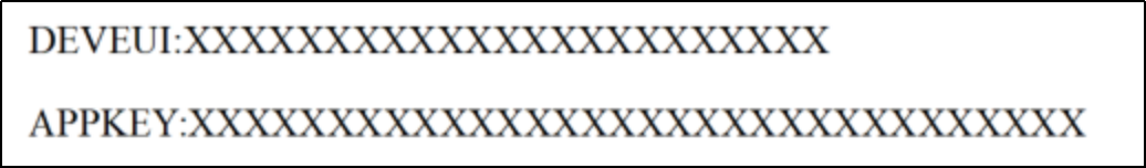
Scan the QR code on the Ai-LoRaWS-1001 sensor enclosure to obtain the key network join parameters such as node DEVEUI and APPKEY. The parameter format is shown below.
It should be noted that the APPEUI of the sensor is fixed to 0000000000000000.
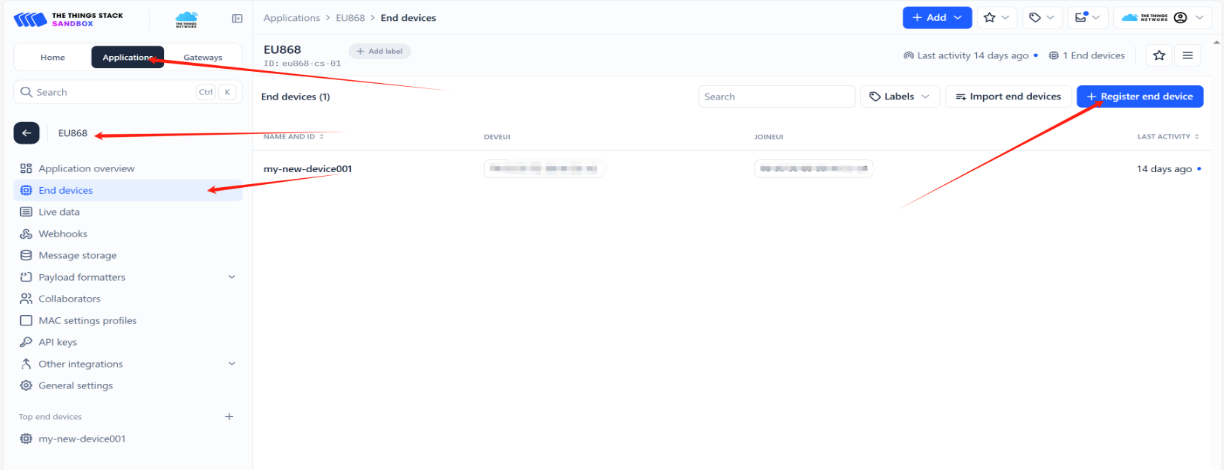
Step 6: Register Node on TTN Platform
Register the end node under the corresponding application.
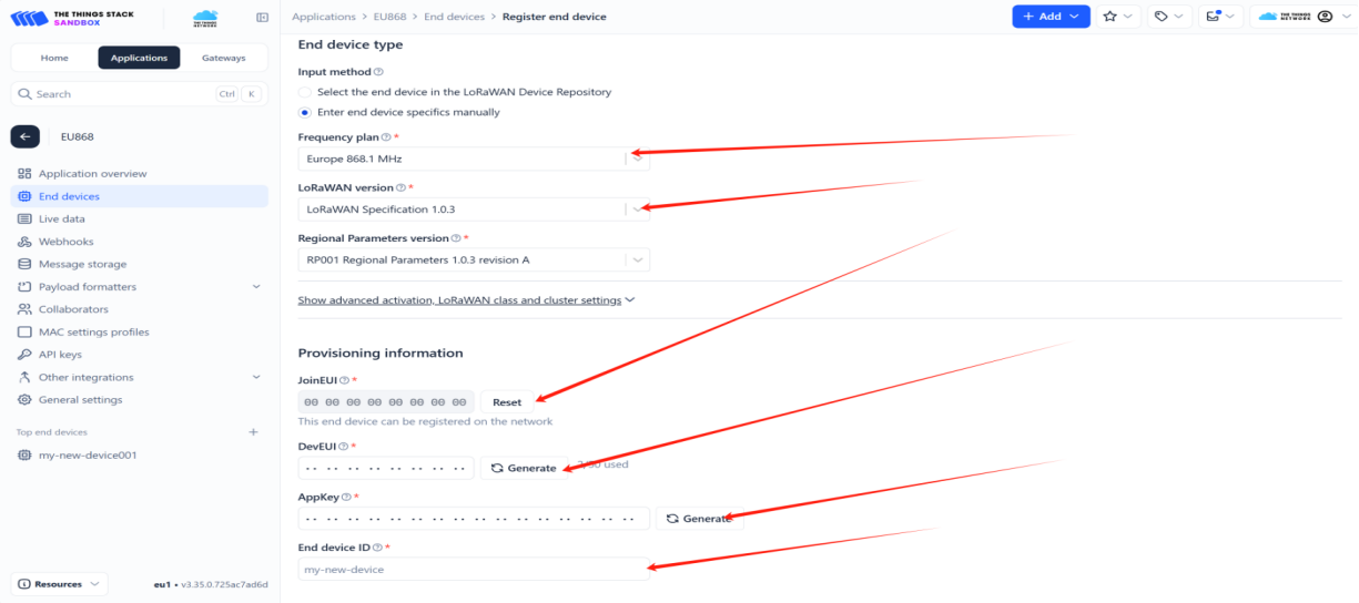
Select the node operating frequency band: Europe 868.1 MHz.
Fill in LoRaWAN version, regional parameters, JoinEUI, DevEUI, AppKey, and other information.
Step 7: Gateway Network Configuration
The gateway supports three network connection methods: Wi-Fi provisioning, Ethernet access, and 4G SIM card access.
Wi-Fi Provisioning Procedure:
Connect the antenna to the device, then connect the power supply.
When powering on the device, press and hold the provisioning button. When the Wi-Fi indicator blinks slowly, the device has entered provisioning mode.
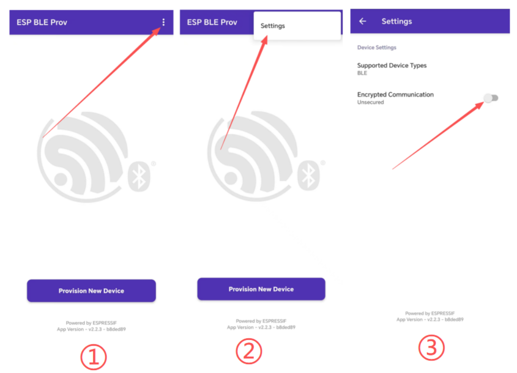
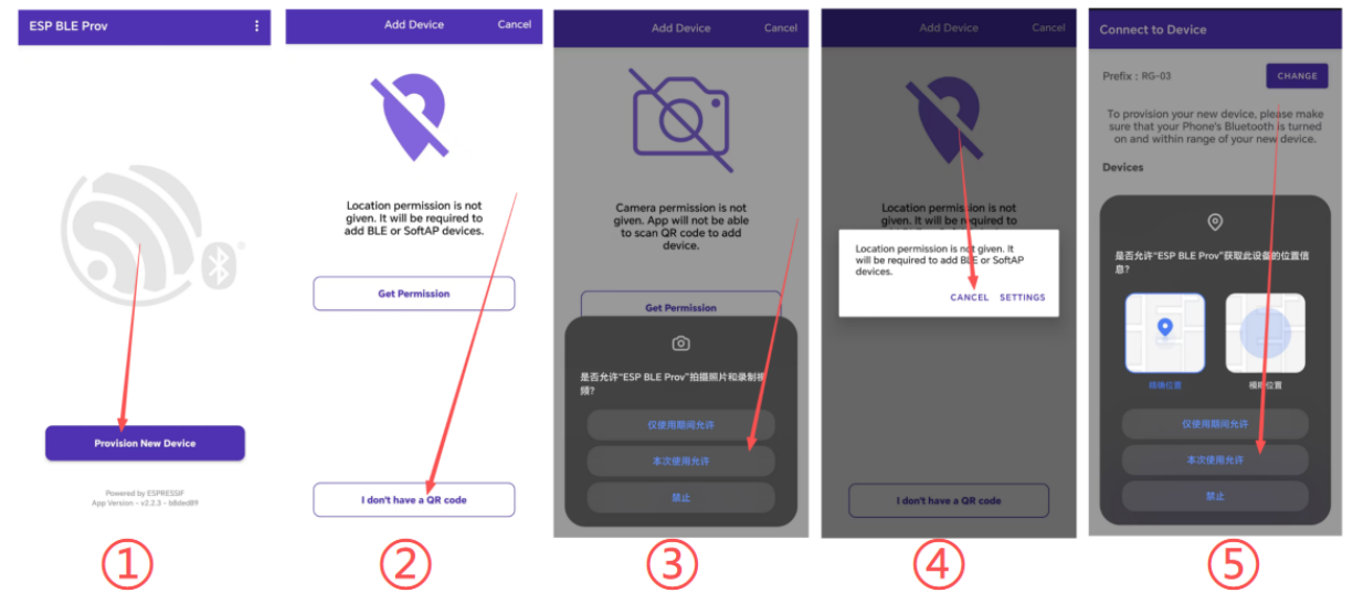
Install the ESP BLE Prov Wi-Fi provisioning app on your mobile phone (obtain the installation package from the official channel), then launch it.
Click the three-dot icon in the upper-right corner → Settings, and disable the default selected Encrypted Communication (unencrypted communication).
Return to the main screen of the app and click Provision New Device to complete permission authorization; If the location permission prompt appears, select CANCEL (location permission can be denied).
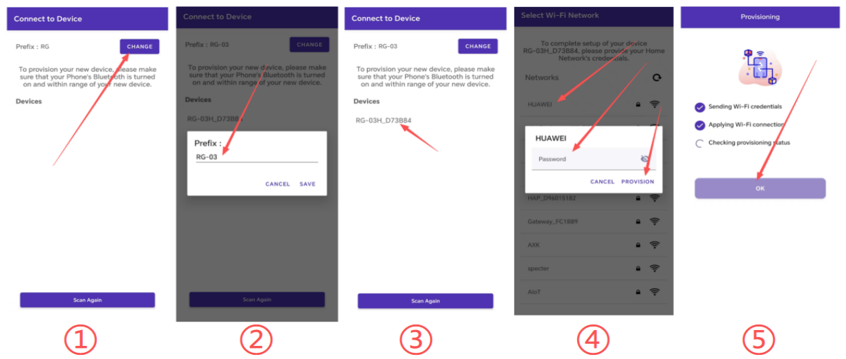
Click I don’t have a QR code, then click CHANGE, and modify the scan name filter to RG-03.
Select the scanned device name to connect, choose the Wi-Fi to be connected and enter the password, then click OK once the network connection is completed.
When the Wi-Fi indicator stays on, provisioning is successful and the device has successfully connected to the server.
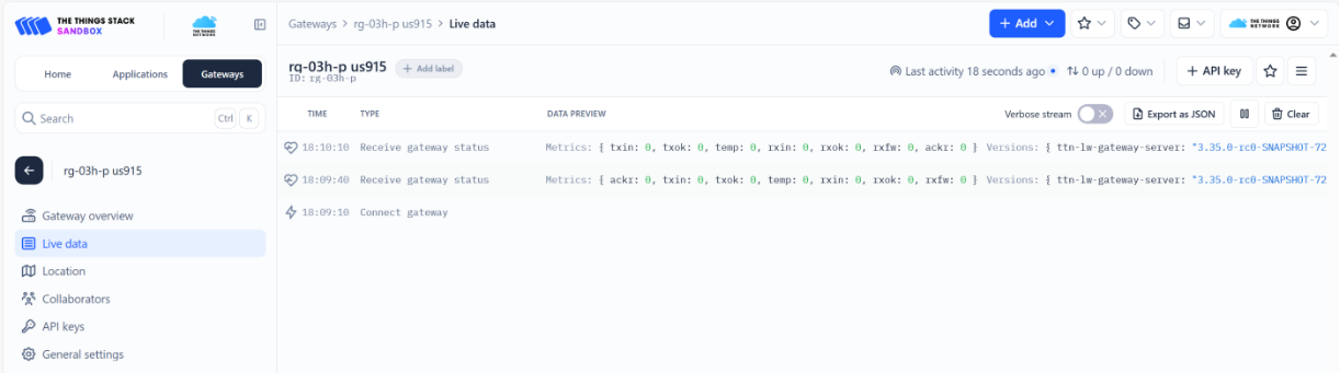
Step 8: Verify Gateway Network Join
After configuring the gateway to connect to the network, view the gateway status and logs in the Live data on the TTN platform to confirm that the gateway has connected to the network successfully.
Step 9: Verify Node Network Join
After confirming that the gateway has successfully connected to the network, send a restart command (Z00000000001) to the sensor via NFC. After completing the configuration and waiting for 5 minutes, check the Live data of the node on the platform to confirm whether the node has successfully joined the network. Refer to Chapter 2 NFC Function Instructions for Sensor for NFC data writing operations and data definitions.
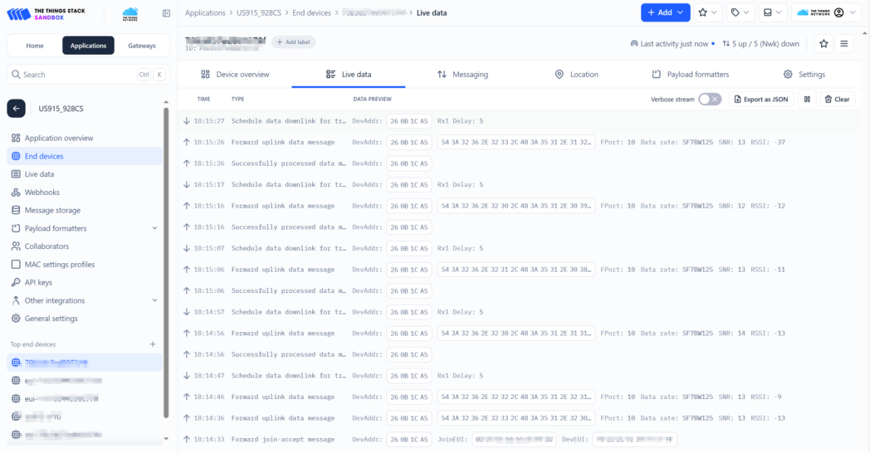
Step 10: Node Data Format Description
Reported Data (HEX):
543A32382E34302C483A35332E3039Corresponding String:
T:28.40,H:53.09(It may also be written asT: 28.40, H: 53.09in the document)Field Definition:
Trepresents temperature,Hrepresents humidity
2. NFC Function Instructions for Sensor
- Install the NFC 标签助手 app to enable NFC read and write functions (obtain from the official channel).
- Launch the app and place the phone close to the NFC antenna to read chip information.
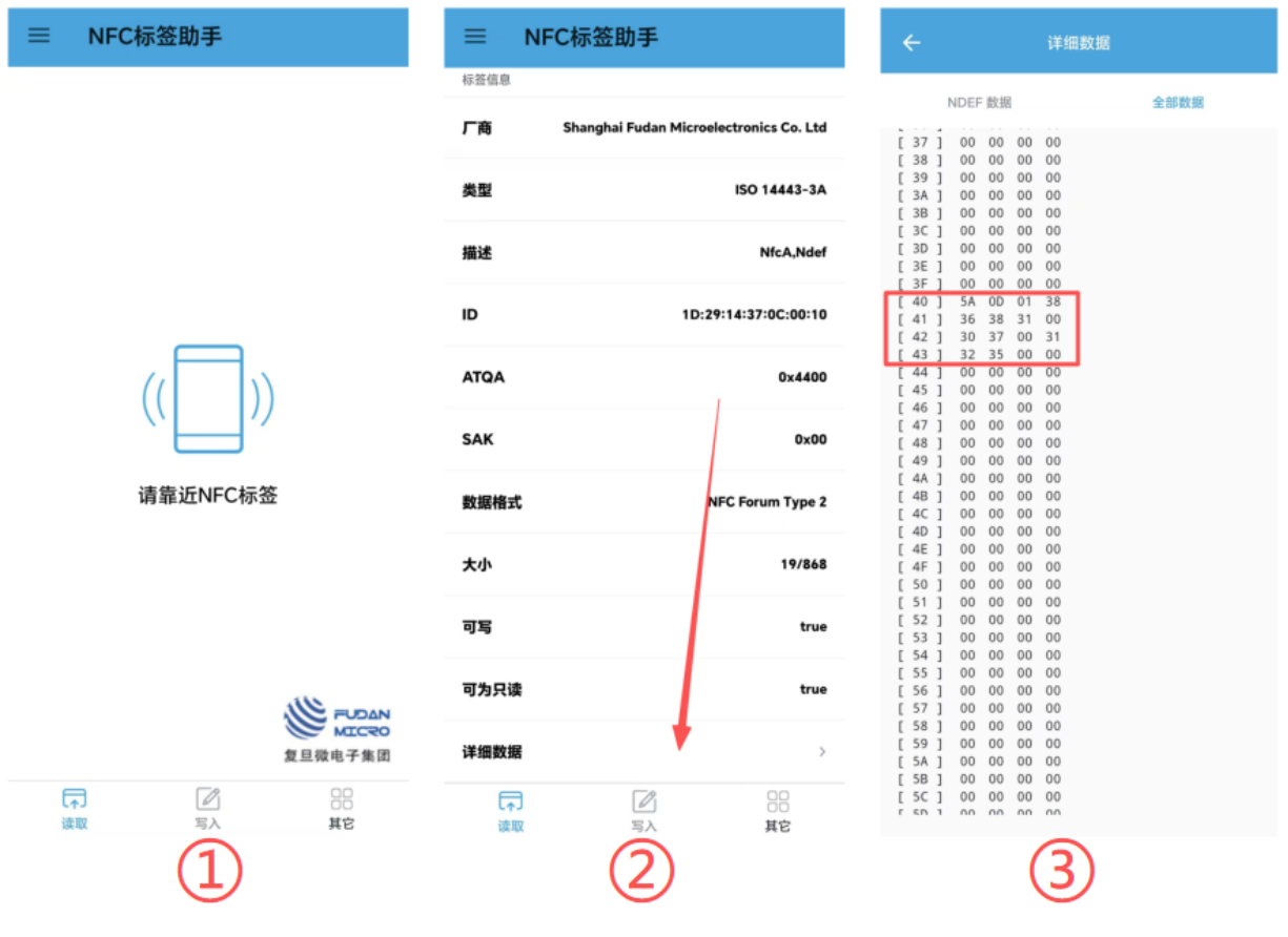
Read Information Format Description (Example):
| Content | Meaning |
|---|---|
5A |
Data header |
0D |
Length |
01 |
Status: executed |
38 36 38 31 00 |
868.1 MHz frequency |
30 37 00 |
Spreading factor SF7 |
31 32 35 00 |
Bandwidth BW125 kHz |
- Select 写入 (Write) → 文本 (Text), enter the configuration information in the text box, click 确定 (OK), and wait for the write operation to complete.
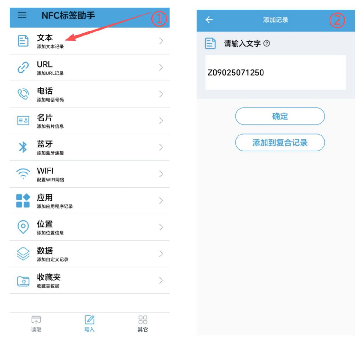
Configuration Information Format Description:
The configuration string is composed of multiple fields concatenated in the protocol-defined order (the execution bit must be configured to the executable state when sending; after execution, the status will be updated to prevent repeated execution). Refer to the table below for field descriptions.
| Field No. | Code Segment | Field Description | Parsing Description | Example Value |
|---|---|---|---|---|
| 1 | Z | Protocol header | ASCII character Z, HEX 0x5A |
0x5A |
| 2 | 0 | Execution status | 0 = not executed; 1 = executed successfully; 2 = executed unsuccessfully(When issuing a command, it must be configured as 0 for the command to be executed; after execution, it will change to 1 or 2) |
0 indicates not executed |
| 3 | 9025 | Frequency | Value divided by 10, unit: MHz | 9025 → 902.5 MHz |
| 4 | 7 | Spreading factor | Usually ranges from SF7 to SF12 | 7 → SF7 |
| 5 | 125 | Bandwidth | Common: 125 kHz, 250 kHz, 500 kHz | 125 → 125 kHz |
| 6 | 0 | Restart flag | 0 = no restart; 1 = restart |
0 indicates no restart |
3. Web Interface Instructions for RG-03H Gateway
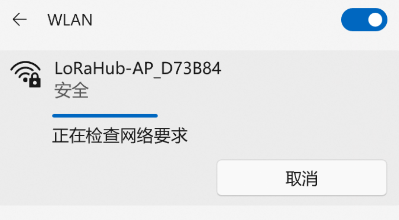
Connect to the gateway hotspot. The hotspot name is
LoRaHub-AP_XXXXXX, with the default password12345678.After successful connection, access the following URL via browser:
http://192.168.4.1:8000.
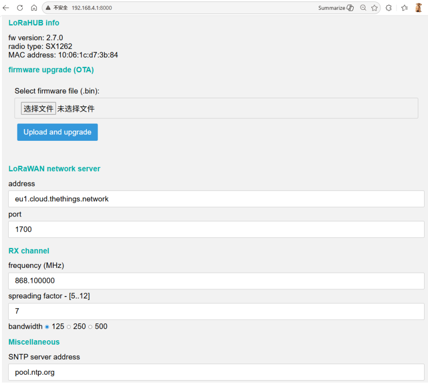
Web interface supports: configure receive channel frequency and bandwidth, SNTP server, hotspot account and password, OTA firmware upgrade, etc.
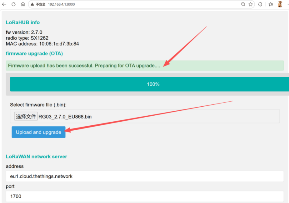
4. OTA Upgrade Instructions for RG-03H Gateway
- Open the RG-03H gateway web interface. In the firmware upgrade (OTA) section, select and upload the OTA firmware file to be upgraded.
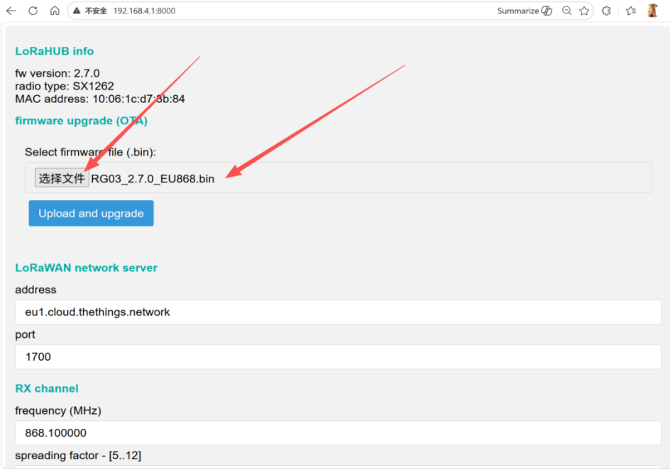
- After the OTA file is successfully uploaded, click Upload and upgrade and wait for the OTA upgrade prompt to complete the firmware upgrade.
Contact Us
The above content helps you quickly get started with the RG-03H gateway and Ai-LoRaWS-1001 sensor solution. For more documents, please refer to the official website and documentation portal.
- Official Website: https://www.ai-thinker.com
- Development DOCS: https://docs.ai-thinker.com/
- Official Forum: http://bbs.ai-thinker.com
- Technical Support: support@aithinker.com